
Dimensions
As any other manufacturing process, MIM also entails some design requirements. Our experienced engineers support customer’s component design from the planning stage until its series production in order to exploit the full potential of MIM technology.
MIM is particularly suitable for small to medium-sized components. As a rule, the bigger a component is the more deviations can occur regarding the component size. Therefore, MIMplus Technologies has specialized in the production of parts with an average weight between 0.01 and 50 g, although the production of larger components is also possible. MIMplus is currently manufacturing components with a maximum weight of about 100 g.
General tolerances
Our experts work with you hand-in-hand to determine the tolerances which depend on the size and material. At an early stage, when considering MIM as a manufacturing process you achieve optimum component design and minimize tolerances. The following table summarizes standard values of typical tolerances. The increasing tolerance becomes clearly visible with an increasing dimension.
|
Nominal dimension / mm |
Tolerance / mm |
|
< 3 |
|
|
3 – 6 |
± 0,06 |
|
6 – 15 |
± 0,075 |
|
15 – 30 |
± 0,15 |
|
30 – 60 |
± 0,25 |
|
> 60 |
± 0,5% of the nominal dimension |
The following geometric guidelines are the most important criteria for successful production of MIM components. In the component design, these criteria should be considered at the earliest possible stage. Targeted implementation reduces rework or avoids additional calibration steps - thus optimizing the costs.
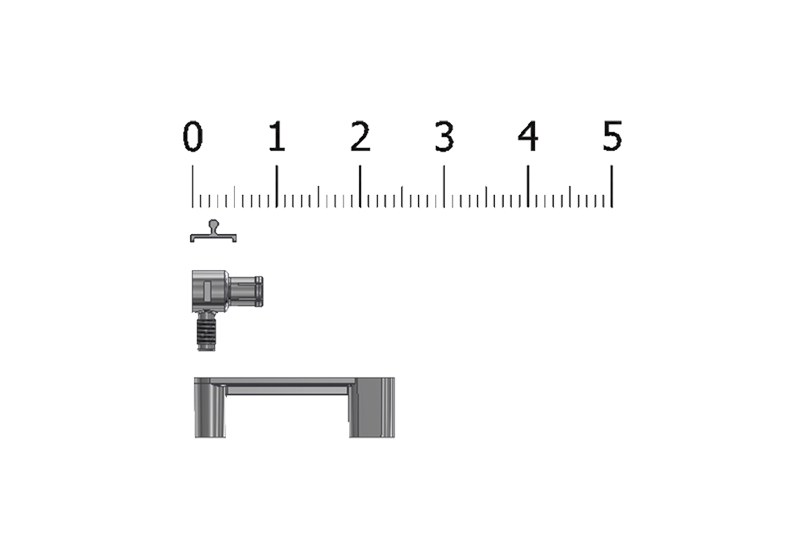
 Contact surface
In the course of de-binding and sintering processes MIM components must be placed on a ceramic sintering tray. In order to prevent deformation of the components during these production steps, components should have as flat contact surface as possible. In case this flatness cannot be realised in the component design, our experts have an extensive expert knowledge in sintering these components without distortion by means of proficient variants of support surfaces or easily removable supports.
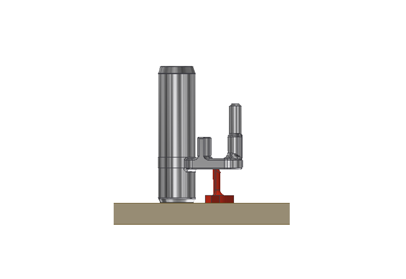
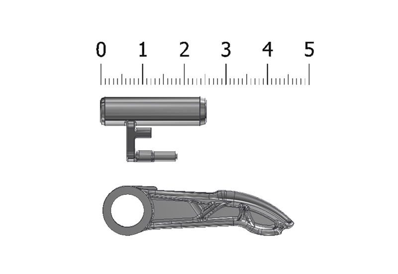
Support structures
In addition to the requirement to prevent or minimize distortion, a stable position of the components is also possible. Components that tend to fall over during transportation can be stabilized by supports.
Furthermore, an appropriate choice of material can compensate for the lack of a plane surface.
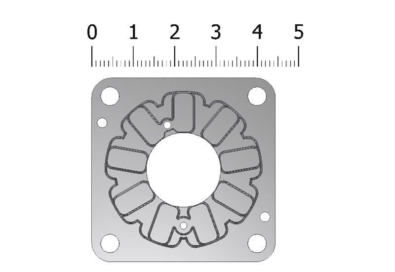
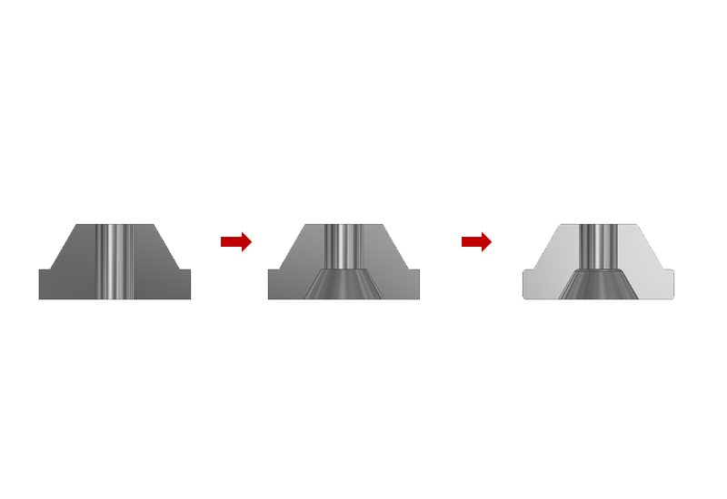
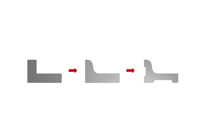 Wall thickness distribution
Constant and even wall thicknesses ensure the highest degree of dimensional accuracy and reproducibility. This makes it possible to significantly reduce the weight of the component and save raw materials, which also has a direct impact on component costs.
In addition to material savings, the risk of blowholes, sink marks and distortion after sintering can be significantly reduced. The even wall thickness enables the consistent component shrinkage over the entire component and thus helps to master the problems mentioned above. Core removal is also a popular solution to avoid material accumulation.
Material cross-section
The minimum possible wall thickness of a MIM component ranges from 0.3 - 0.5 mm., Material cross sections of > 5 mm should be avoided at most.
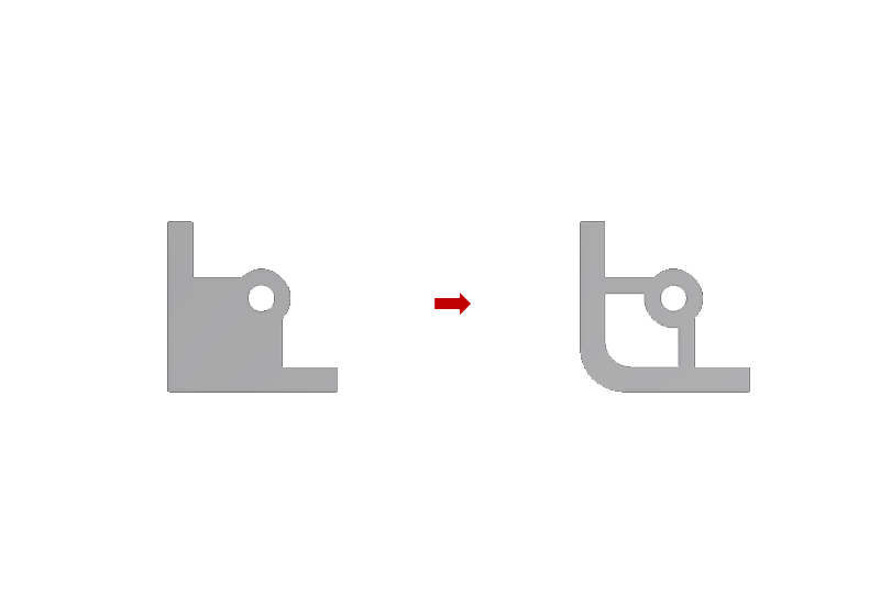
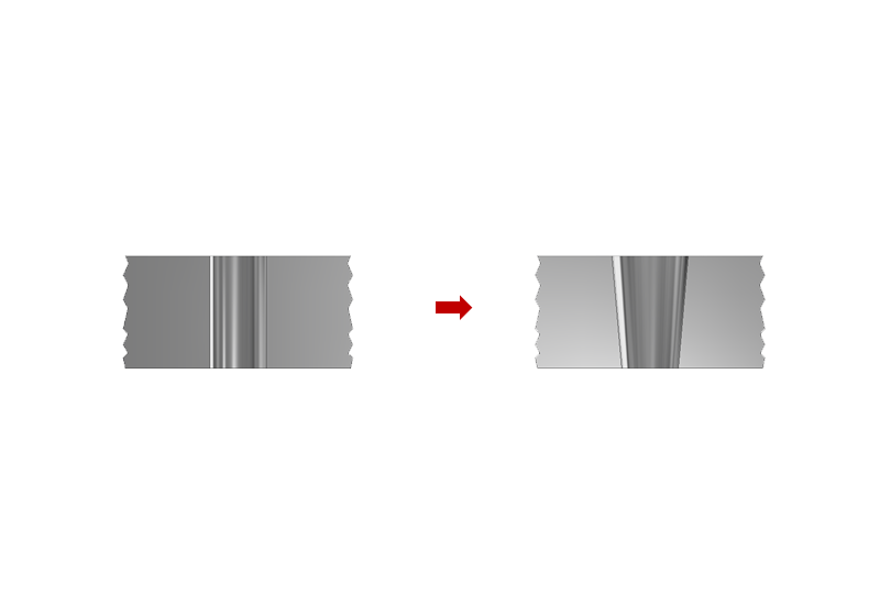
Transitions
In general, rounded edges are preferable to sharp edges. This improves mold filling during the injection molding process and enables the cavity to be filled without segregation. Furthermore, due to the reduced notch effect, this also has a positive effect on the mechanical properties of the “green part” and the sintered part.
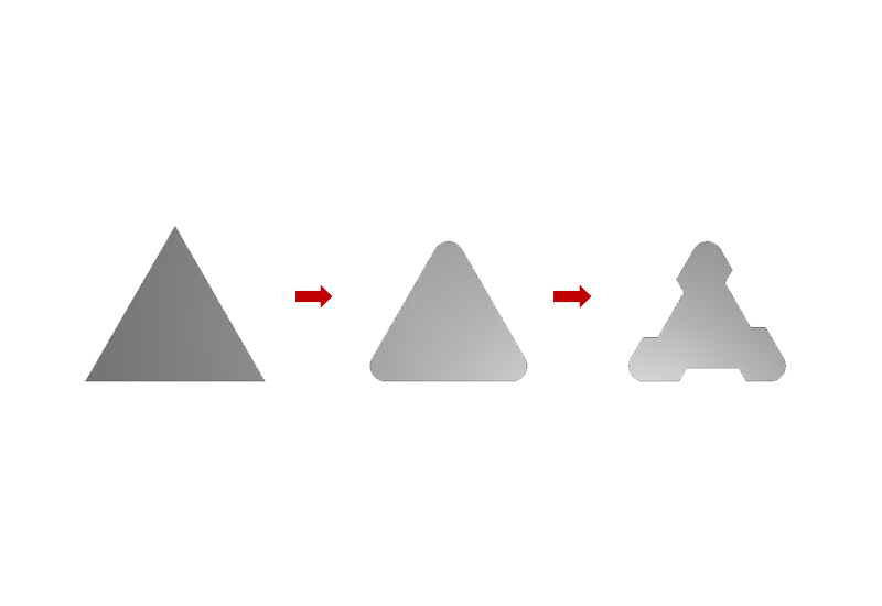
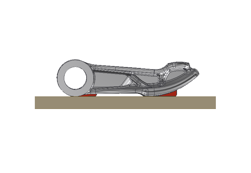
 Draft angles
As for parts made of plastic injection molding, draft angles are also advantageous in the MIM process. Draft angles of 1° are typically recommended. For very small geometries, these angles can sometimes be omitted. However, in every case, this has to be decided depending on the component.
Choice of the injection point
For optimum filling of the injection mold, injection points should be located near thick-walled areas. This prevents early freezing of the feedstock at the end of the injection molding cycle and reduces the risk of blowholes and cavities. For visible components, it should be ensured that the injection point is selected so that it is not within the visible range of the component. Thus, the cost-intensive post-processing steps can be avoided.
A suitable design of the injection point eliminates or reduces visible segregation of the feedstock. With the help of filling simulations, we determine the ideal position and geometry of the injection point together with the customer.
Our experts look forward to discussing these design guidelines in detail in order to successfully develop and produce MIM components according to your demands.